kirra-docs

Modify Toolbar

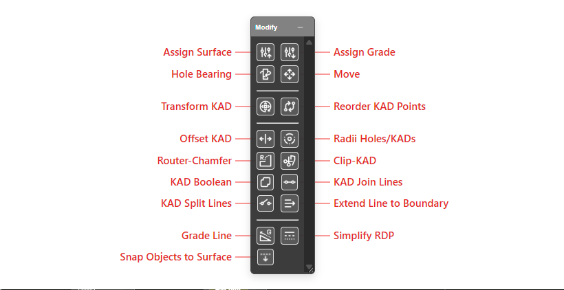
The Modify toolbar provides tools for transforming, editing, and manipulating blast holes and KAD entities. It is one of the seven floating toolbars available on the right side of the Kirra workspace.


Toolbar Overview

The Modify toolbar contains the following tools:

Tool Type Description
Assign Surface Interactive Set collar elevation from a loaded surface
Assign Grade/Toe Dialog Set grade or toe elevation from a surface with multiple assignment modes
Hole Bearing Interactive Change hole bearing by dragging
Move Interactive Move selected holes or KAD entities
Transform KAD Dialog Translate and rotate KAD entities by offset and bearing/pitch/roll
Offset KAD Dialog Offset lines and polygons inward or outward
Radii Dialog Create circular polygons around selected holes or KAD points
Router-Chamfer Interactive Create routed or chamfered edge transitions on selected geometry
Clip-KAD Interactive Clip selected KAD objects against a boundary polygon
Reorder KAD Points Dialog Change the start vertex and winding direction of lines/polygons
KAD Boolean Dialog 2D boolean operations (union, difference, intersection, XOR) on polygons
Join KAD Lines Dialog Join two lines end-to-end into a single entity
Split KAD Lines Dialog Split a line or polygon at one or more vertices
Extend Line to Boundary Interactive Extend the end of a line until it reaches a chosen boundary entity
Grade Line Interactive Set a constant slope (grade) along a selected line
Simplify RDP Interactive Reduce a line/polygon’s vertex count with the Ramer–Douglas–Peucker algorithm

Assign Surface (Collar)

Sets the collar (start) elevation of selected blast holes by interpolating Z values from a loaded surface.

Select Surface for Collar dialog

How to Use

  1. Select the blast holes to update
  2. Click the Assign Surface button in the Modify toolbar
  3. If multiple surfaces are loaded, a dialog prompts you to choose one
  4. Collar Z values are interpolated from the surface at each hole’s XY position
  5. Hole lengths and toe positions are recalculated

Notes


Assign Grade/Toe Elevation

Sets grade or toe elevation from a loaded surface, with four assignment modes that control how related hole attributes are recalculated.

Assign Grade/Toe Elevation dialog

Assignment Modes

Mode Description Recalculates
Assign GRADE (calc Toe from Subdrill) GradeZ is set from the surface. ToeZ = GradeZ - Subdrill/cos(angle) Length, ToeXYZ
Assign TOE (calc Grade from Subdrill) ToeZ is set from the surface. GradeZ = ToeZ + Subdrill/cos(angle) Length, GradeXYZ
Assign GRADE (keep Toe, calc Subdrill) GradeZ is set from the surface. Toe stays in position. Subdrill = ToeZ - GradeZ (along hole) Subdrill
Assign TOE (keep Grade, calc Subdrill) ToeZ is set from the surface. Grade stays in position. Subdrill = ToeZ - GradeZ (along hole) Subdrill

How to Use

  1. Select the blast holes to update
  2. Click the Assign Grade button in the Modify toolbar
  3. Choose a surface (if multiple are loaded)
  4. Select the assignment mode
  5. Click Apply

Hole Bearing

Interactively changes the bearing of selected blast holes by dragging on the canvas.

How to Use

  1. Select the blast holes to update
  2. Click the Hole Bearing button in the Modify toolbar
  3. Click and drag on the canvas to set the bearing angle
  4. The bearing is calculated from the drag direction (0° = North, clockwise)

Move

Moves selected blast holes or KAD entities to a new position by dragging.

How to Use

  1. Select the holes or KAD entities to move
  2. Click the Move button in the Modify toolbar
  3. Click and drag on the canvas to move the selection
  4. Release to place at the new position

Transform KAD

Translates and rotates selected KAD entities by specified offsets and angles.

Transform dialog

Parameters

Parameter Description
X Offset Horizontal (Easting) displacement in metres
Y Offset Vertical (Northing) displacement in metres
Z Offset Elevation displacement in metres
Bearing Rotation about the Z axis (degrees)
Pitch Rotation about the X axis (degrees)
Roll Rotation about the Y axis (degrees)

How to Use

  1. Select the KAD entities to transform
  2. Click the Transform KAD button in the Modify toolbar
  3. Enter the offset and rotation values
  4. Click Apply

Offset KAD

Offsets KAD lines and polygons inward or outward by a specified distance, creating new parallel entities.

Offset KAD dialog

Parameters

Parameter Description
Offset (m) Distance to offset. Positive expands (outward for polygons, left for lines), negative contracts
Projection (°) Slope angle for offset. 0° = horizontal, positive = up slope, negative = down slope
Number of Offsets How many parallel offsets to create (1 or more)
Priority Mode Distance Priority (total distance) or other modes
Offset Colour Colour for the new offset entities [VERIFY: UI label spelling]
Handle Crossovers Automatically resolve self-intersections in the offset result
Keep Elevations Interpolate Z values from the original entity
Limit to Elevation Constrain the offset to a fixed elevation

Notes

Where the output lands

Design → Offsets, named <source>_Offset_<distance>m_<uid> — for example Crest_Offset_5m_p7q1. See Layer Organisation.

How to Use

  1. Select a line or polygon entity
  2. Click the Offset KAD button in the Modify toolbar
  3. Configure the offset parameters
  4. Click Offset

Radii (Create Radii Polygons)

Creates circular polygons around selected blast holes or KAD points.

Create Radii Polygons dialog

Parameters

Parameter Description
Radius (m) Circle radius. Positive expands, negative contracts
Circle Steps Number of vertices in each circle (more steps = smoother)
Rotation Offset (°) Rotate the circle. 0° = no rotation, +45° = clockwise, -45° = counter-clockwise
Starburst Offset (%) 100% = circle, 50% = even points at half radius, 0% = star shape
Point Location Which hole point to use: Start/Collar Location or other options
Line Width Width of the polygon outline
Polygon Colour Colour for the generated polygons [VERIFY: UI label spelling]
Union Circles Combine overlapping circles into a single polygon

Notes

Where the output lands

Boundaries → Radii → Polygons, named <blast>_Radii_<radius>m_<uid> — for example Blast01_Radii_300m_k3f9.

See Layer Organisation.

How to Use

  1. Select blast holes or KAD point entities
  2. Click the Radii button in the Modify toolbar
  3. Configure the radius and options
  4. Click Create

Router-Chamfer

Creates routed (rounded) or chamfered (bevelled) edge transitions on selected KAD geometry — softening sharp corners on a polygon or line.

How to Use

  1. Select the KAD line or polygon to modify
  2. Click the Router-Chamfer button in the Modify toolbar
  3. Choose the transition style and size [VERIFY: exact dialog options]
  4. Apply the result

Clip-KAD

Clips selected KAD objects against a boundary polygon, keeping the portion inside (or outside) the boundary. The 2D drawing counterpart to the surface Clip Surface tool.

How to Use

  1. Select the KAD entities to clip
  2. Click the Clip-KAD button in the Modify toolbar
  3. Pick the boundary polygon
  4. Choose which side to keep and apply [VERIFY: exact keep-inside/outside control]

Reorder KAD Points

Changes the start vertex and winding direction of KAD line and polygon entities. Useful for controlling the direction of offset operations and ensuring consistent polygon winding.

Reorder KAD - Set Direction dialog

How to Use

  1. Select a line or polygon entity
  2. Click the Reorder KAD Points button in the Modify toolbar
  3. Click on the vertex you want to become the new start point
  4. Choose the winding direction: Left (Counter-clockwise) or Right (Clockwise)
  5. Click OK

Notes


KAD Boolean

Performs 2D boolean operations on KAD polygon entities. Supports Union, Intersection, Difference, and XOR operations.

KAD Boolean Operation dialog

Parameters

Parameter Description
Subject (A) The primary polygon (pick from canvas or dropdown)
Clip (B) The clipping polygon (pick from canvas or dropdown)
Operation Union (A + B), Intersect, Difference (A - B), or XOR
Output Colour Colour for the result polygon [VERIFY: UI label spelling]
Line Width Width of the result polygon outline
Sub-layer Name Sub-layer under Analysis for the output (default Booleans)

Operations

Where the output lands

Analysis → Booleans, named <subject>_<Operation>_<uid> — for example Poly01_Union_f5g7. Type a different Sub-layer Name to file it under Analysis → <your name> instead. See Layer Organisation.

How to Use

  1. Click the KAD Boolean button in the Modify toolbar
  2. Click the pick button next to Subject (A) and click a polygon on the canvas
  3. Click the pick button next to Clip (B) and click another polygon
  4. Select the operation
  5. Click Execute

Join KAD Lines

Joins two KAD lines end-to-end into a single entity.

Join KAD Lines dialog

Parameters

Parameter Description
Line A First line (pick from canvas)
Line B Second line (pick from canvas)
Weld Tolerance Maximum distance between endpoints to join (default: 0.01)
New Entity Name Name for the joined entity (default: “Joined”)
Close as Poly Close the result into a polygon
Delete Originals Remove the original lines after joining

How to Use

  1. Click the KAD Join Lines button in the Modify toolbar
  2. Click the pick button next to Line A and click a line on the canvas
  3. Click the pick button next to Line B and click another line
  4. Configure options (entity name, close as poly, delete originals)
  5. Click Join to join and keep the dialog open, or Join & Close to join and close

Notes


Split KAD Lines

Splits a KAD line or polygon at one or more selected vertices, creating separate entities from the pieces.

Split KAD dialog

How to Use

  1. Click the KAD Split Lines button in the Modify toolbar
  2. Click on a line or polygon on the canvas to select it
  3. Click on vertices along the entity to mark split points
  4. Click an already-selected vertex to deselect it
  5. The dialog shows a live preview of the split result
  6. Optionally check Delete Original to remove the source entity
  7. Click Split to split and keep the dialog open, or Split & Close to split and close

Split Behaviour

Source Type Split Points Result
Line N points N+1 open lines
Polygon N points (min 2) N closed pieces or open lines

Notes


Extend Line to Boundary

Extends the end of a selected line until it reaches a chosen boundary entity (another line or a polygon edge), so two strings meet cleanly at an intersection.

How to Use

  1. Click the Extend Line to Boundary button in the Modify toolbar
  2. Click the line you want to extend, near the end to extend
  3. Click the boundary entity to extend to
  4. The line is lengthened to the intersection point

Grade Line

Sets a constant slope (grade) along a selected line — each vertex’s elevation is placed on a straight gradient between the line’s ends, giving a uniform grade (useful for drains, batters, and haul-grade strings).

How to Use

  1. Click the Grade Line button in the Modify toolbar
  2. Select the line to grade
  3. Set the target slope (or start/end elevations) [VERIFY: exact dialog inputs]
  4. Apply — vertex Z values are recomputed to follow the constant grade

Simplify RDP

Reduces the vertex count of a line or polygon using the Ramer–Douglas–Peucker algorithm, removing points that don’t materially change the shape — handy for cleaning up dense survey strings or digitised boundaries.

How to Use

  1. Click the Simplify RDP button in the Modify toolbar — an active-mode banner appears
  2. Click a line or polygon to simplify it
  3. Repeat on other entities as needed
  4. Right-click to exit the tool

Tune the simplification tolerance to trade fidelity against vertex count. [VERIFY: where the tolerance is set]


Recent Changes (March 2026)

The following improvements were made to the Modify toolbar tools in recent updates:

Recent Changes (August 2026)