kirra-docs
Connect Toolbar
The Connect toolbar groups every control that draws, edits, or interprets timing connections between holes — surface connectors, electronic detonator timing, harness-wire assignment, and the temporal mesh display. It is one of the floating toolbars on the right side of the Kirra workspace.
Toolbar Overview
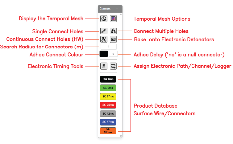 The Connect toolbar with all controls labelled.
The Connect toolbar contains the following controls:
| Control | Type | Purpose |
|---|---|---|
| Display the Temporal Mesh | Toggle | Show / hide the universal temporal mesh (time as Z) |
| Temporal Mesh Options | Dialog | Configure temporal-mesh appearance and behaviour |
| Single Connect Holes | Tool | Draw one source → target connector at a time |
| Connect Multiple Holes | Tool | Cascade a chain of connectors in one operation |
| Continuous Connect Holes (HW) | Tool | Click-by-click chain that stays active for the next chain (v1.0.230) |
| Bake onto Electronic Detonators | Action | Fold surface-cascade delays into electronic primer offsets |
| Search Radius for Connectors (m) | Input | Snap radius used when picking source / target holes |
| Adhoc Connect Colour | Picker | Colour for adhoc connectors |
| Adhoc Delay | Input | Delay (ms) for adhoc connectors — na is a null connector |
| Electronic Timing Tools | Dialog | Open the Electronic Timing dialog and temporal-mesh construct editor |
| Assign Electronic Path/Channel/Logger | Dialog | Set harness wire path / channel / commander on selected primers |
| Product Database (Surface Wire / Connectors) | List | Pick the surface connector product used by Single / Multi / Continuous connect |
Display the Temporal Mesh
Toggles the temporal mesh on or off. The temporal mesh is the triangulated surface in plan view where Z represents firing time in milliseconds, not ground elevation. When visible, it gives an immediate read of the firing order across the whole pattern.
How to use
- Click the Display the Temporal Mesh button on the Connect toolbar to toggle visibility
- Mesh appearance is configured via Temporal Mesh Options (below)
See Electronic Timing Constructs for how the mesh is built.
Temporal Mesh Options
Opens the temporal mesh configuration dialog — controls for appearance and behaviour of the universal temporal mesh.
[SCREENSHOT NEEDED: Temporal Mesh Options dialog]
How to use [VERIFY: full options list against current build]
- Click the Temporal Mesh Options button on the Connect toolbar
- Adjust mesh display (wireframe / filled / contour-only)
- Adjust time-to-elevation scale
- Close the dialog
Single Connect Holes
Draws one surface connector from a source hole to a target hole, using the currently selected product (the highlighted entry in the Product Database list at the bottom of the toolbar).
How to use
- Click the Single Connect Holes button on the Connect toolbar
- Click the source hole (the hole that fires first)
- Click the target hole (the hole that fires after, with the product’s delay)
- A connector line appears between the two holes
- Repeat — the tool stays active for the next single connection
Notes
- The source hole’s coloured product chip in the Product Database list is the connector type that will be drawn
- The connector uses the snap radius set in Search Radius for Connectors (m)
- Each connection sets From Hole and Delay on the target hole
Connect Multiple Holes
Cascades a chain of surface connectors across a set of holes in one operation.
How to use [VERIFY: pick-by-click vs lasso behaviour]
- Click the Connect Multiple Holes button on the Connect toolbar
- Click successive holes to define the chain — each click adds the next link with the current product’s delay
- Right-click or press
Escapeto terminate the chain - The tool returns to idle (does not auto-restart a new chain)
Continuous Connect Holes (HW)
Third connector mode alongside Single and Multi. Click-by-click chain continues until an explicit terminator (Escape, right-click, or double-click). The tool stays active for the next chain so you can snake row-by-row tie-ups without returning to the toolbar between rows.
Introduced in v1.0.230.
How to use
- Click the Continuous Connect Holes (HW) button on the Connect toolbar
- Click successive holes to build the chain
- Press
Escape, right-click, or double-click to terminate the current chain - The tool stays active — click another source hole to start the next chain
- Click the toolbar button again (or change tool) to exit Continuous mode
Stadium-zone preview
A stadium-shape preview is drawn live in both 2D and 3D as you hover — showing the swept area around the proposed connector.
Bake onto Electronic Detonators
Folds the current surface-cascade delays into the electronic primer timing fields. After baking, the firing time stored on each primer reflects the cumulative cascade so the temporal mesh and electronic detonator firing match.
How to use
- Make sure the pattern has both surface connectors and Electronic detonators in the charging design
- Click the Bake onto Electronic Detonators button on the Connect toolbar
- Confirm any prompt to overwrite existing electronic offsets
- The baked offsets are written to
primer.timeOffsetMsfor every Electronic primer in scope
Note: This is the same Bake-Delay action available in the footer of the Time Window dialog.
Search Radius for Connectors (m)
The pick radius used by Single, Multi, and Continuous connect when snapping to source / target holes. Default shown in the screenshot is 1.
How to use
- Click the input box and enter the radius in metres
- Larger values are forgiving on dense patterns; smaller values force precise clicks
Adhoc Connect Colour
Colour used for adhoc connectors — connectors drawn without a fixed surface connector product. The picker swatch shows the current colour.
How to use
- Click the colour swatch
- Pick a colour
- New adhoc connectors use this colour until changed
Adhoc Delay
Delay value (ms) applied to adhoc connectors that don’t belong to a surface connector product. Default shown is 0.
| Value | Meaning |
|---|---|
Numeric (e.g. 25) |
Adhoc connector with this delay |
na |
Null connector — draws the line but contributes zero to the timing chain (cosmetic / topology only) |
Electronic Timing Tools
Opens the Electronic Timing dialog — the temporal-mesh construct editor where you draw timing contours, set relief or time-range parameters, and assign holes to a construct.
Visibility rule
The Electronic Timing toolbar group is shown automatically when the loaded charging data includes at least one Electronic detonator on any hole (from v1.0.46). It stays hidden when no electronic detonators are present. There is no global “enable experimental electronics” toggle.
How to use
- Make sure at least one hole has an Electronic primer in the charging design
- Click the Electronic Timing Tools button on the Connect toolbar
- The dockable Electronic Timing dialog opens
- Draw a timing contour (polyline or Bézier), set start time and relief (or two contours and a time range), assign holes, and click Apply & Keep Offsets or Apply & Reset Offsets
See Electronic Timing Constructs for the full reference.
Assign Electronic Path/Channel/Logger
Opens the Harness Wire Assignment dialog — set the harness path, channel, logger, and commander IDs on selected SurfaceWire / Electronic primers using HarnessElectronicSystemSpecs.
Visibility rule
Same visibility rule as Electronic Timing Tools — appears when charging includes Electronic detonators.
How to use
- Select the holes / primers to assign
- Click the Assign Electronic Path/Channel/Logger button on the Connect toolbar
- Choose the path, channel, logger, and commander from the system specs
- Click Apply
See Harness Wire Assignment for the full reference.
Product Database (Surface Wire / Connectors)
The vertical list at the bottom of the toolbar shows the currently loaded surface connector products — these are the delays available to Single / Multi / Continuous connect. The labelled screenshot shows:
| Chip | Type | Delay |
|---|---|---|
| HW 0ms | Harness Wire | 0 ms |
| SC 9ms | Surface Connector | 9 ms |
| SC 17ms | Surface Connector | 17 ms |
| SC 25ms | Surface Connector | 25 ms |
| SC 42ms | Surface Connector | 42 ms |
| SC 67ms | Surface Connector | 67 ms |
| SC 109ms | Surface Connector | 109 ms |
How to use
- Click a chip to set it as the active connector product for new connections
- The active product is what Single / Multi / Continuous connect will draw with
- Products come from the loaded charging design — load a different products CSV to change the available chips
See Products CSV Reference for product file format.
Related topics
- Timing Sequences — connector workflow and timing concepts
- Electronic Timing Constructs — temporal mesh and electronic detonator timing
- Harness Wire Assignment — path / channel / commander IDs
- Time Window Dialog — timing analysis (FFT, IDI, Detune, Constrain)
- Holes Toolbar — placing and editing holes
- Interface Tour — workspace overview