kirra-docs
Your First Blast — Step-by-Step Walkthrough
This guide walks through a complete blast design from a blank workspace — define a pattern template, place holes (rectangular block or inside a polygon), load explosive products, build a deck, draw timing connectors, and animate the blast.
If you haven’t already, read the Interface Tour so the App Navigation Bar, side panel, and floating toolbars are familiar.
All screenshots in this walkthrough were captured on Kirra v1.0.240 running in Chrome at
kirra-design.com.
Before You Start
- A modern desktop browser (Chrome / Edge recommended), or the Kirra desktop installer
- No data needed — we’ll build everything from scratch
Step 1 — Open the Pattern Templates Library
A Pattern Template is a reusable bundle of design defaults (diameter, burden, spacing, sub-drill, hole angle, row direction, blast-name pattern). You define it once, then drop it on the canvas as a block of holes or inside a polygon.
Open the Pattern Templates dialog from the highlighted button on the Holes floating toolbar.
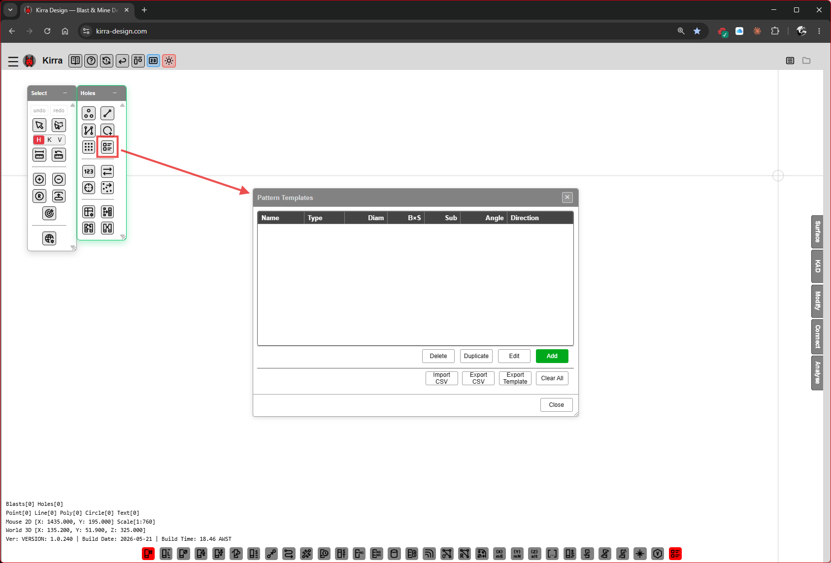 The Holes toolbar (red-boxed button) opens the Pattern Templates dialog.
The list is empty on first launch. Columns: Name, Type, Diam, B×S, Sub, Angle, Direction.
Footer buttons:
| Button | Purpose |
|---|---|
| Delete | Remove the selected template |
| Duplicate | Copy the selected template |
| Edit | Open the selected template for editing |
| Add (green) | Create a new template |
| Import CSV | Load templates from CSV |
| Export CSV | Save templates to CSV |
| Export Template | Export a single template file |
| Clear All | Remove every template |
| Close | Close the dialog |
Click Add to create your first template.
Step 2 — Define the Pattern Template
The Add Pattern Template dialog opens.
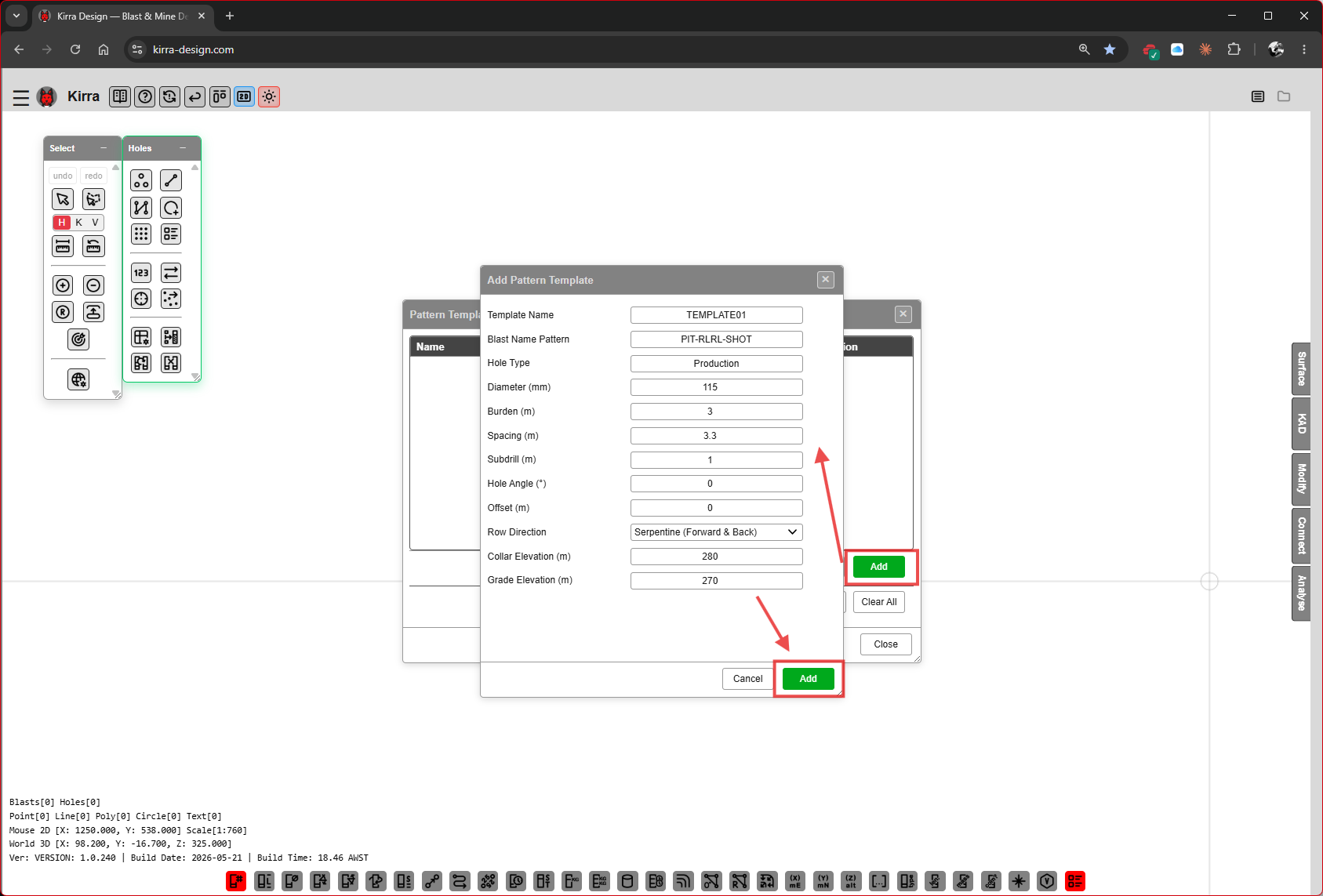 Fill the template fields, then click the green Add button.
Fields (with the values shown in the screenshot):
| Field | Example value | Purpose |
|---|---|---|
| Template Name | TEMPLATE01 |
Label used to pick this template later |
| Blast Name Pattern | PIT-RLRL-SHOT |
Default blast-name prefix for holes placed with this template |
| Hole Type | Production |
Production / Buffer / Trim / Presplit [VERIFY: full enum] |
| Diameter (mm) | 115 |
Hole diameter |
| Burden (m) | 3 |
Spacing between rows |
| Spacing (m) | 3.3 |
Spacing along a row |
| Subdrill (m) | 1 |
Length below grade |
| Hole Angle (°) | 0 |
0 = vertical |
| Offset (m) | 0 |
Row-to-row offset for staggered patterns |
| Row Direction | Serpentine (Forward & Back) |
How rows alternate |
| Collar Elevation (m) | 280 |
Default collar Z |
| Grade Elevation (m) | 270 |
Default grade (toe) Z |
Click the green Add button (bottom right) to save the template.
Step 3 — Verify and Close
The template now appears in the list, highlighted.
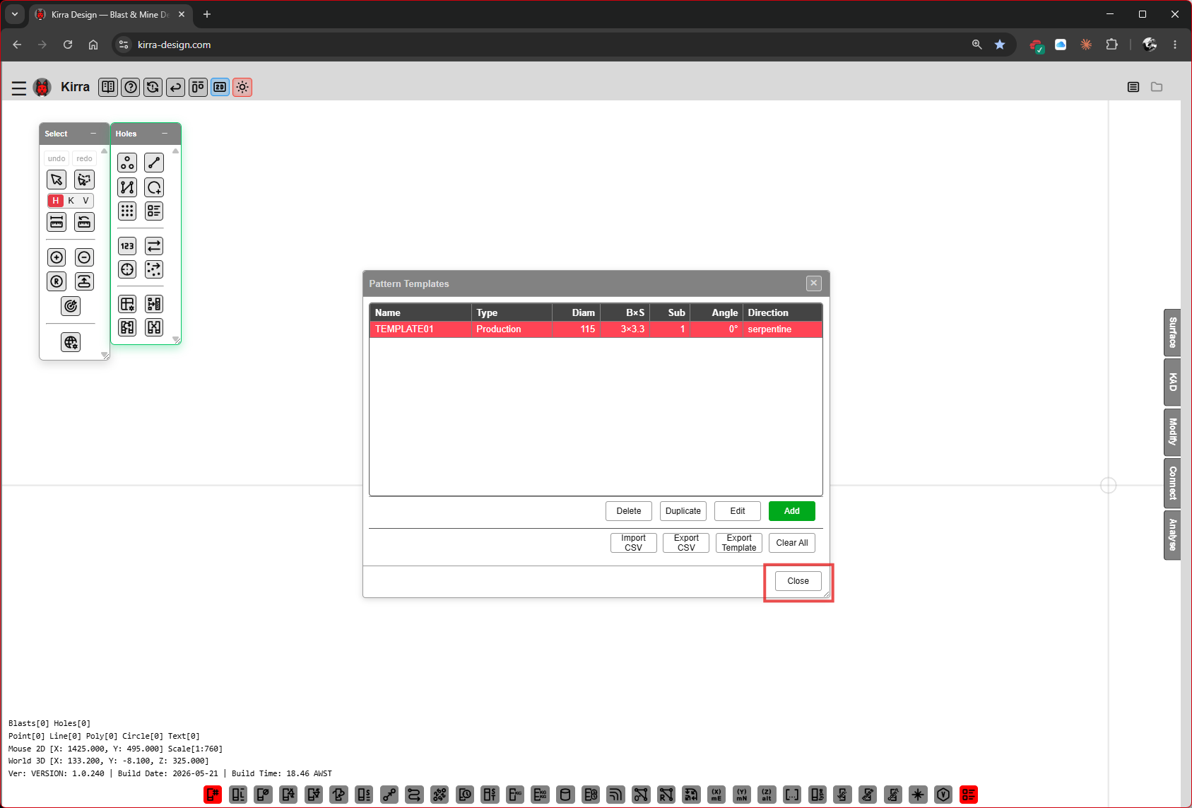
TEMPLATE01 saved — type Production, 115 mm, 3×3.3 BxS, 1 m sub-drill, 0° angle, serpentine direction.
Click Close to dismiss the Pattern Templates dialog.
Step 4 — Option A: Place a Block of Holes
The simplest layout — a rectangular grid that uses your template’s burden, spacing, and direction.
Open the Add Pattern Block dialog from the highlighted button on the Holes toolbar.
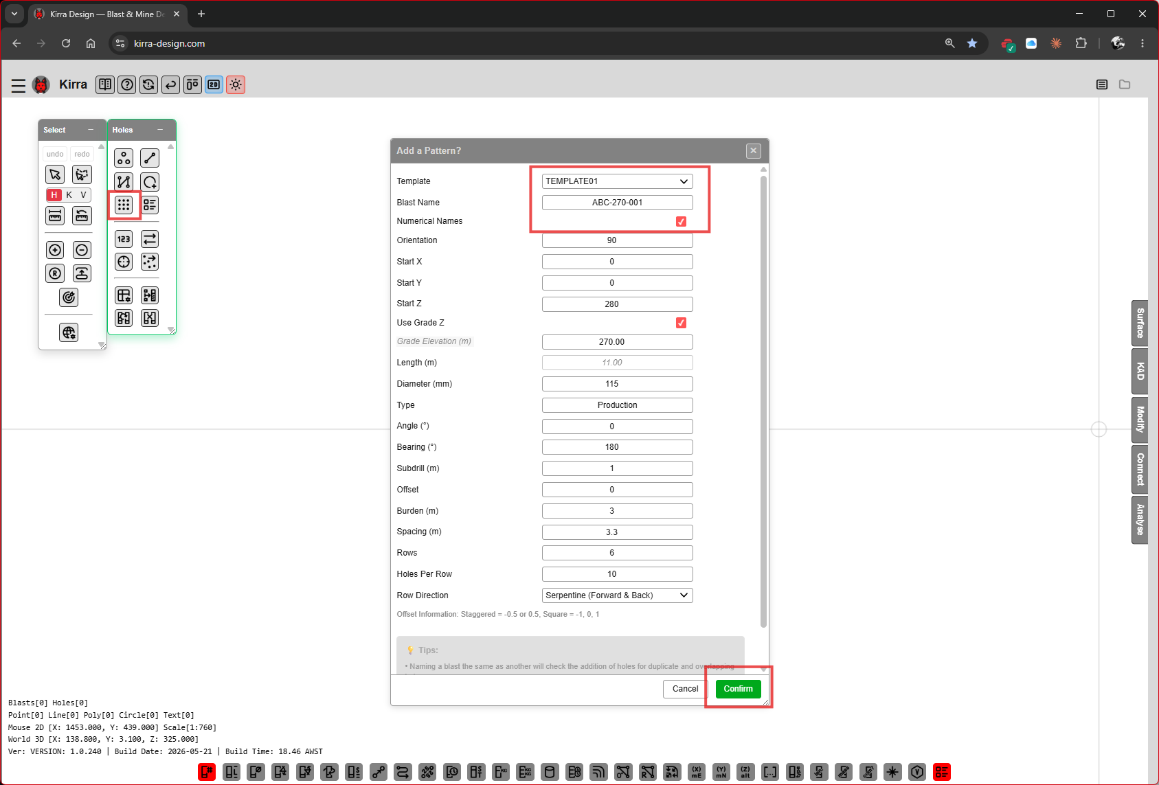 Add a Pattern? dialog — Template dropdown locked to
 TEMPLATE01, Blast Name set to ABC-270-001, Numerical Names ticked.
Fields (with the values shown):
| Field | Example | Purpose |
|---|---|---|
| Template | TEMPLATE01 |
Pick the template defined in Step 2 |
| Blast Name | ABC-270-001 |
Name for this blast (the entity name in the TreeView) |
| Numerical Names | ☑ | Use numeric hole IDs (1, 2, 3…) |
| Orientation | 90 |
Pattern orientation in degrees |
| Start X / Y / Z | 0 / 0 / 280 |
Pattern origin (collar Z = 280 from template) |
| Use Grade Z | ☑ | Compute toe from grade elevation |
| Grade Elevation (m) | 270.00 |
Pulled from template |
| Length (m) | 11.00 |
Hole length from collar to toe |
| Diameter (mm) | 115 |
From template |
| Type / Angle / Bearing | from template | |
| Subdrill / Offset | from template | |
| Burden / Spacing | 3 / 3.3 |
From template |
| Rows | 6 |
|
| Holes Per Row | 10 |
|
| Row Direction | Serpentine (Forward & Back) |
From template |
The footer note reads:
Staggered ≈ -0.5 or 0.5, Square ≈ -1, 0, 1. Tip: Naming a blast the same as another will check the addition of holes for duplicate and increment.
Click Confirm to place the block.
Step 4A — Block Placed
A 6-row × 10-hole grid appears on the canvas, numbered 1 → 60 in the serpentine row direction.
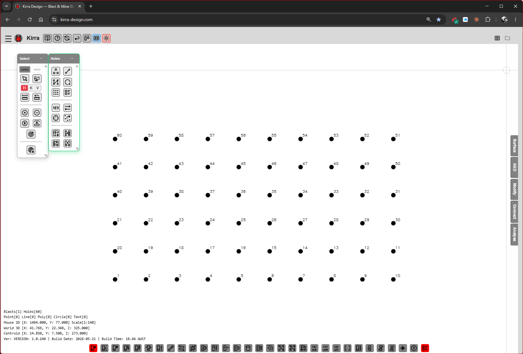 60 holes placed in a 6×10 serpentine block. The Information Overlay (bottom-left) now reads
 Blasts[1] Holes[60].
If a rectangular block is all you need, skip ahead to Step 6 — Build the Product Library.
Step 5 — Option B: Place Holes Inside a Polygon
For an irregular blast boundary, draw a polygon first and then fill it with holes.
Step 5 — Start a drawing layer
On the KAD toolbar, click the Polygon drawing tool (highlighted in red). Kirra prompts you to name the drawing layer the new geometry will live in.
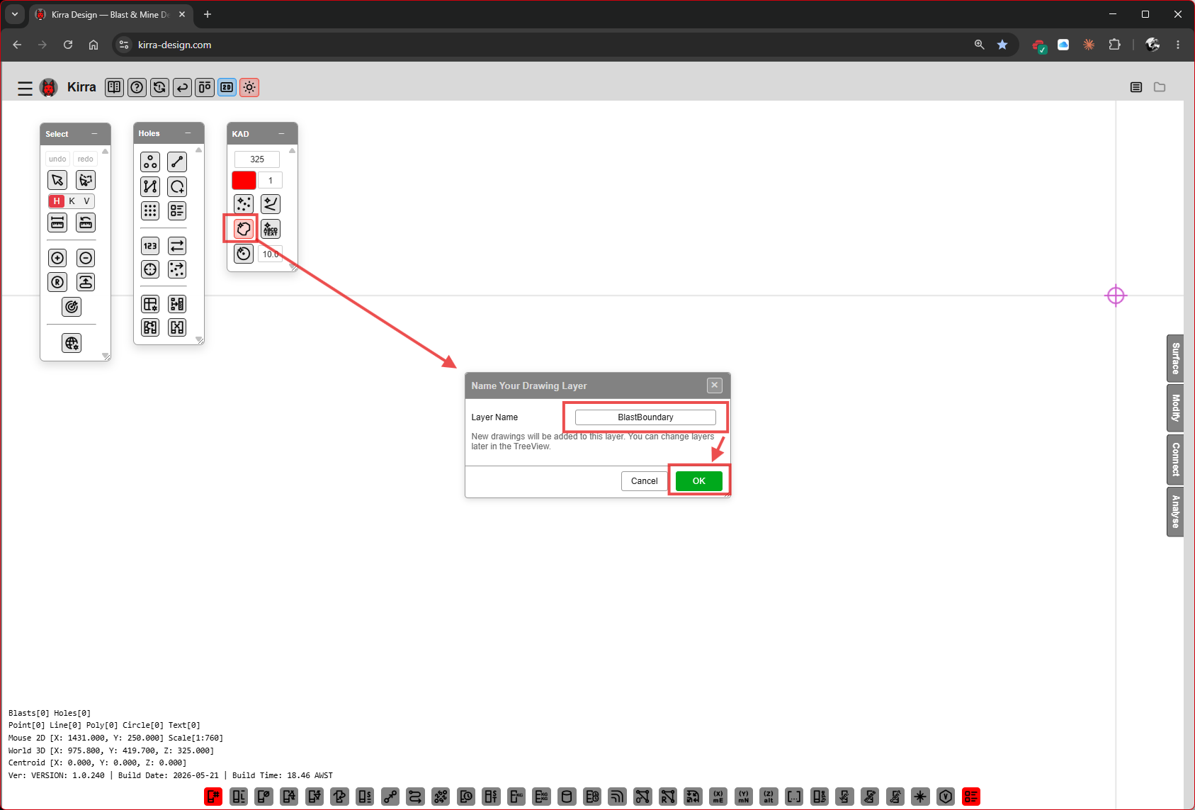 KAD → Polygon tool → “Name Your Drawing Layer” dialog. Type a layer name (e.g.
 BlastBoundary) and click OK.
The helper text on the dialog reads: “New drawings will be added to this layer. You can change layers later in the TreeView.”
Step 5A — Draw the polygon
Click around the canvas to place polygon vertices. Press Escape (or double-click) to close the polygon.
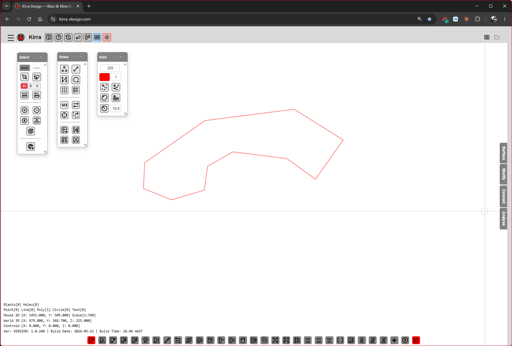 A free-form polygon drawn on the canvas — this will be the blast boundary.
Step 5B — Pick the polygon with the Add Holes In Polygon tool
On the Holes toolbar, click the Add Holes In Polygon button (highlighted), then click the polygon you just drew. Kirra labels the picked polygon with Start and End markers (green) showing the row direction.
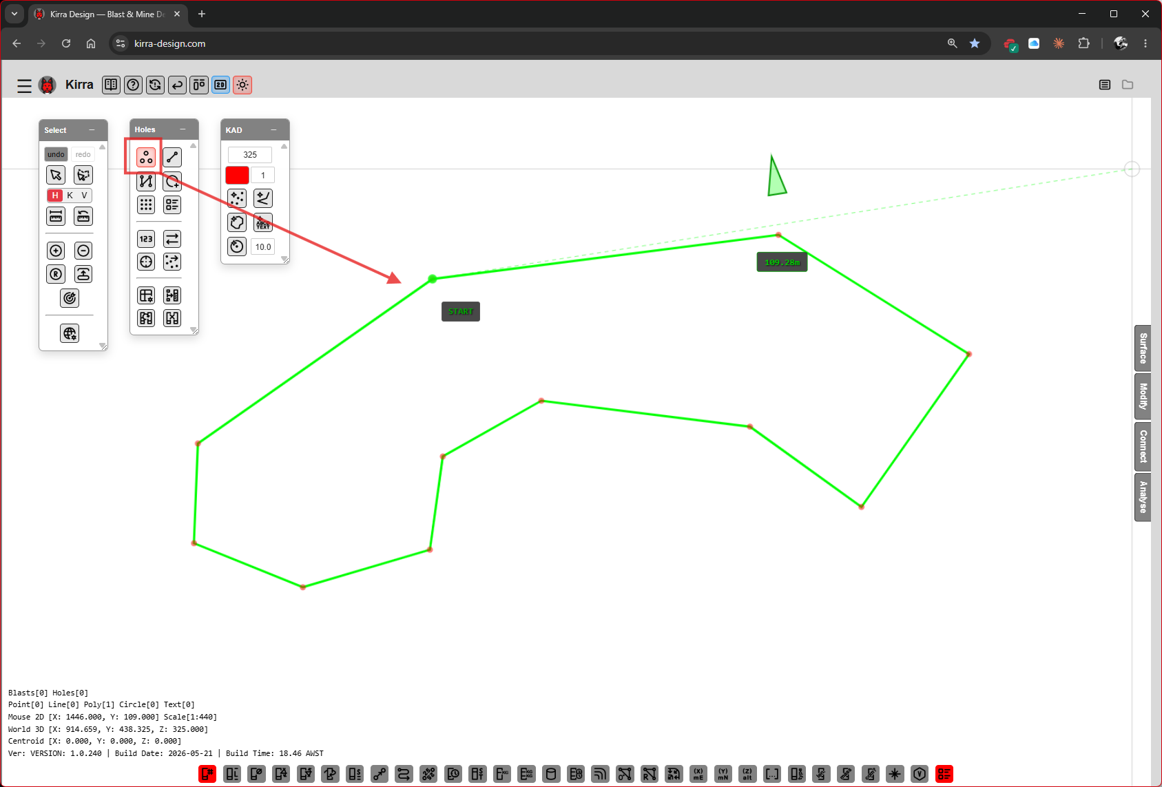 Polygon picked. Green Start / End labels show where the row sweep begins and ends.
Step 5C — Configure the Generate Holes In Polygon dialog
Same template-driven dialog as the block placement, with a couple of polygon-specific fields.
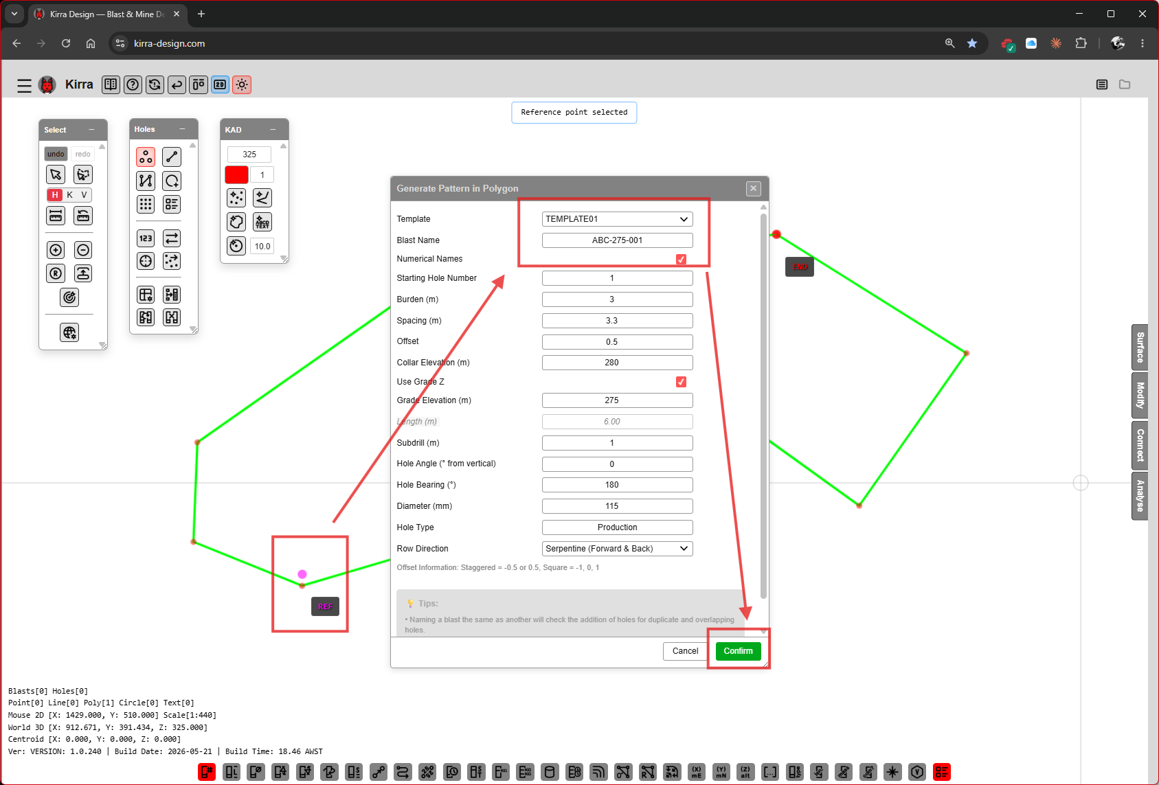 [VERIFY: full field list — screenshot is low-resolution. Confirm Template / Blast Name / Numerical Names / Starting Hole Number / Burden / Spacing / Offset / Collar Z / Use Grade Z / Grade Z / Subdrill / Hole Angle / Hole Bearing / Diameter / Hole Type / Row Direction.]
Click Confirm.
Step 5D — Holes generated
Kirra fills the polygon row-by-row, snapping the rows to the polygon edges using the row-direction setting.
 Holes filling the polygon, numbered along the serpentine sweep.
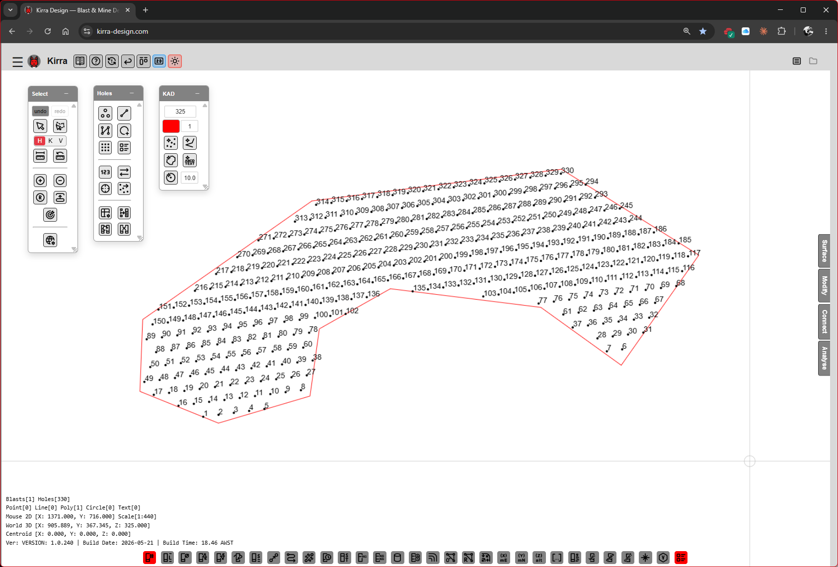
Step 5E — Final polygon-filled pattern
 Pattern after generation — the polygon boundary remains as a KAD layer; holes are a separate blast entity.
Step 6 — Build the Product Library
Before you can charge holes, Kirra needs to know what explosive and non-explosive products you’re using. Open the Product Manager dialog from the highlighted button on the Holes toolbar.
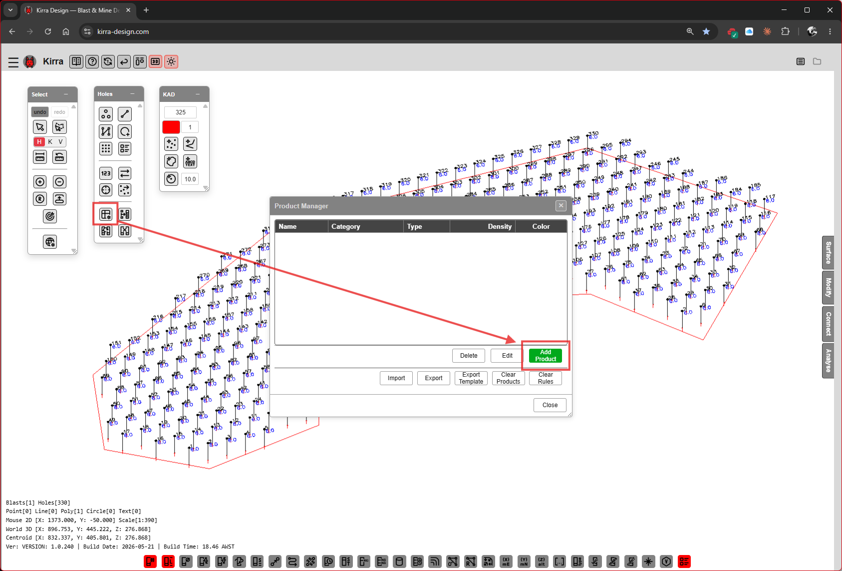 Product Manager opens with an empty list. Click the green Add button to define your first product.
The Product Manager dialog has:
| Element | Purpose |
|---|---|
| Columns | Name, Category, Type, Density, Color |
| Delete / Edit / Add | Modify the product list |
| Import / Export | CSV round-trip of the library |
| Export Template | Export a starter products CSV |
| Clear Products / Clear Rules | Wipe the library |
| Close | Dismiss the dialog |
You’ll add four products in this walkthrough: STEMMING, ANFO (bulk), BOOSTER, and an initiator (DH-400MS).
See Products CSV Reference for the full schema if you want to import a pre-built library instead.
Step 6A — Add STEMMING (non-explosive)
The Add Product sub-dialog opens.
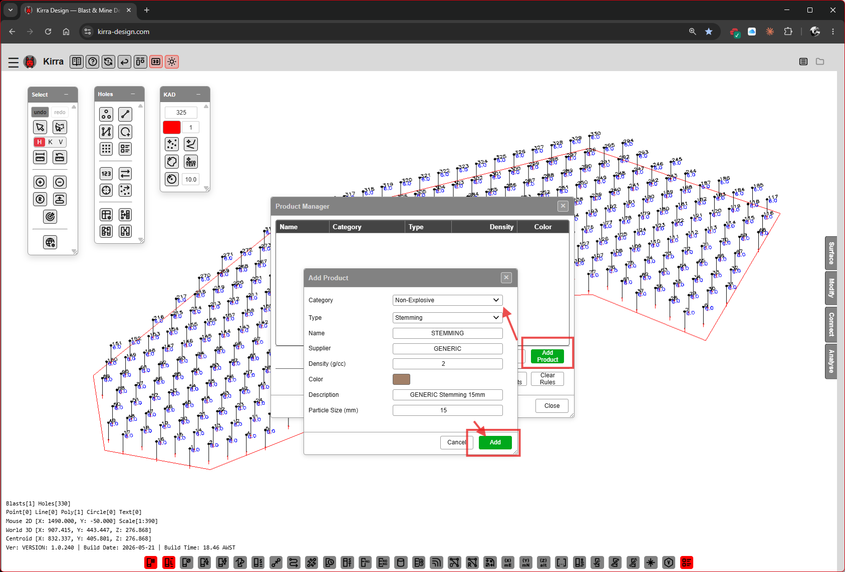
| Field | Value |
|---|---|
| Category | Non-Explosive |
| Type | Stemming |
| Name | STEMMING |
| Supplier | GENERIC |
| Density (g/cc) | [VERIFY: default value] |
| Color | swatch |
| Description | GENERIC Stemming Xmm [VERIFY exact wording] |
| Particle Size (mm) | 10 [VERIFY] |
Click Add.
Step 6B — Add ANFO (bulk explosive)
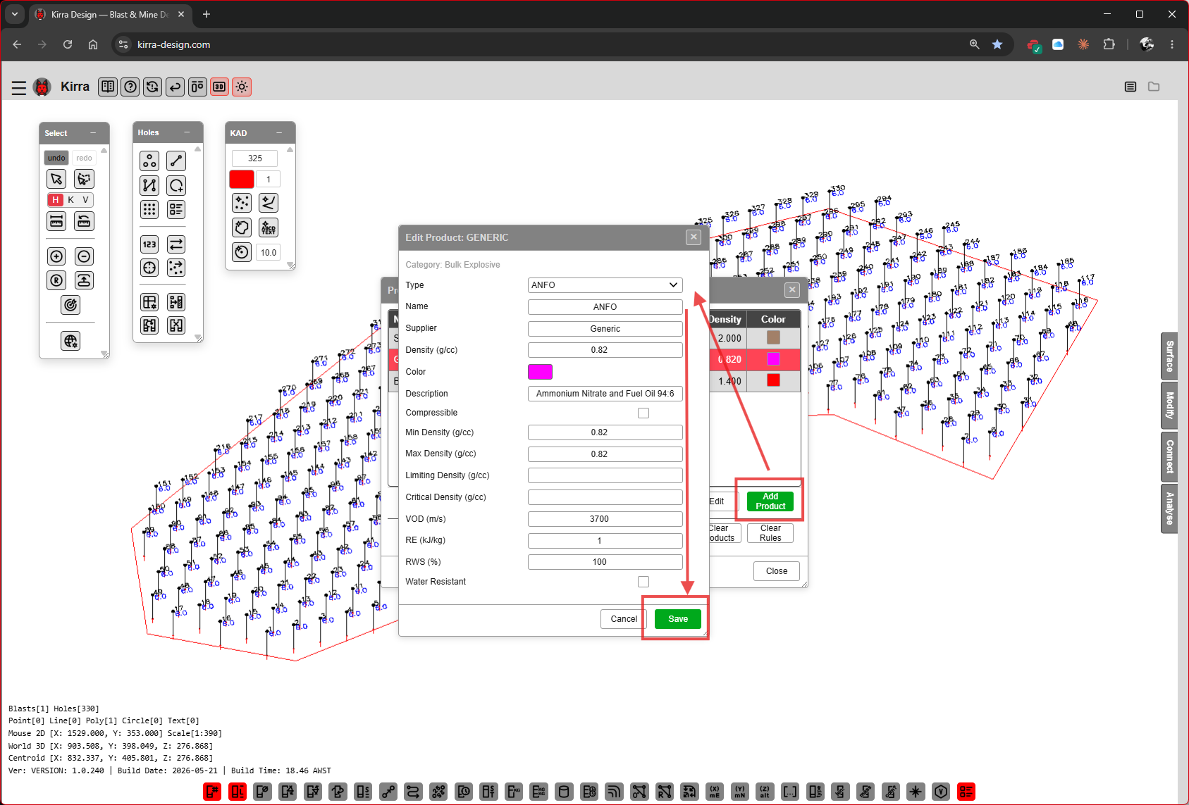
| Field | Value |
|---|---|
| Type | ANFO |
| Name | ANFO |
| Supplier | Generic |
| Cost | [VERIFY] |
| Description | Ammonium Nitrate and Fuel Oil 94:6 |
| Compressible | [VERIFY checkbox state] |
| Min Density (g/cc) | 0.82 |
| Max Density (g/cc) | 0.82 |
| Limiting Density (g/cc) | [VERIFY] |
| Critical Density (g/cc) | [VERIFY] |
| VOD (m/s) | 3700 [VERIFY] |
| PE (kJ/kg) | [VERIFY] |
| Water Resistant | unchecked |
Click Save.
Step 6C — Add BOOSTER (high explosive)
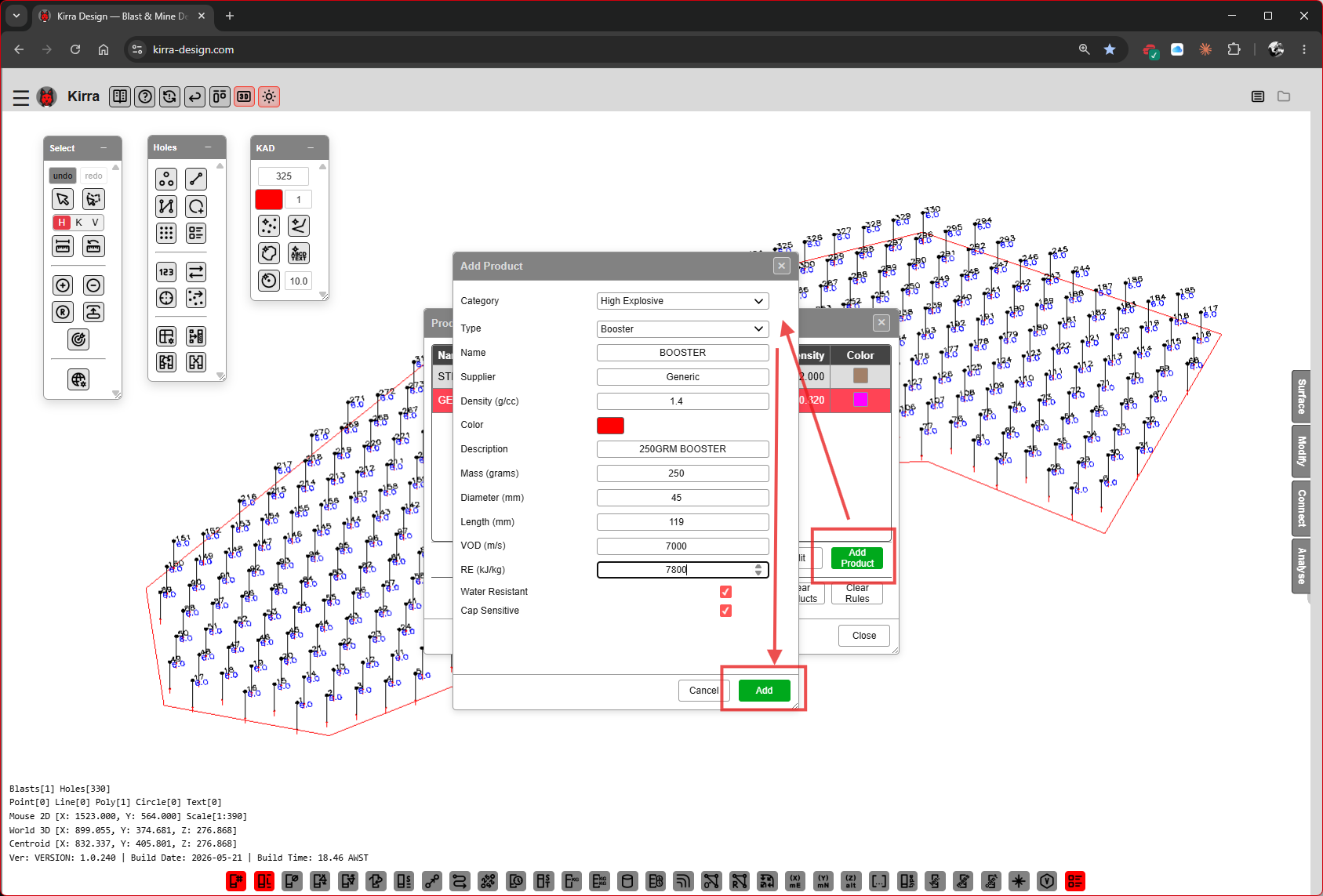
| Field | Value |
|---|---|
| Category | High Explosive |
| Type | Booster |
| Name | BOOSTER |
| Supplier | Generic |
| Density (g/cc) | 1.6 [VERIFY] |
| Color | red swatch |
| Description | XGM/450 BOOSTER [VERIFY exact wording] |
| Mass (grams) | 450 [VERIFY] |
| Diameter (mm) | [VERIFY] |
| Length (mm) | [VERIFY] |
| PE (kJ/kg) | [VERIFY] |
| VOD (m/s) | 7400 [VERIFY] |
| Water Resistant | ☑ |
| Cap Sensitive | [VERIFY] |
Click Add.
Step 6D — Add an initiator (downhole detonator)
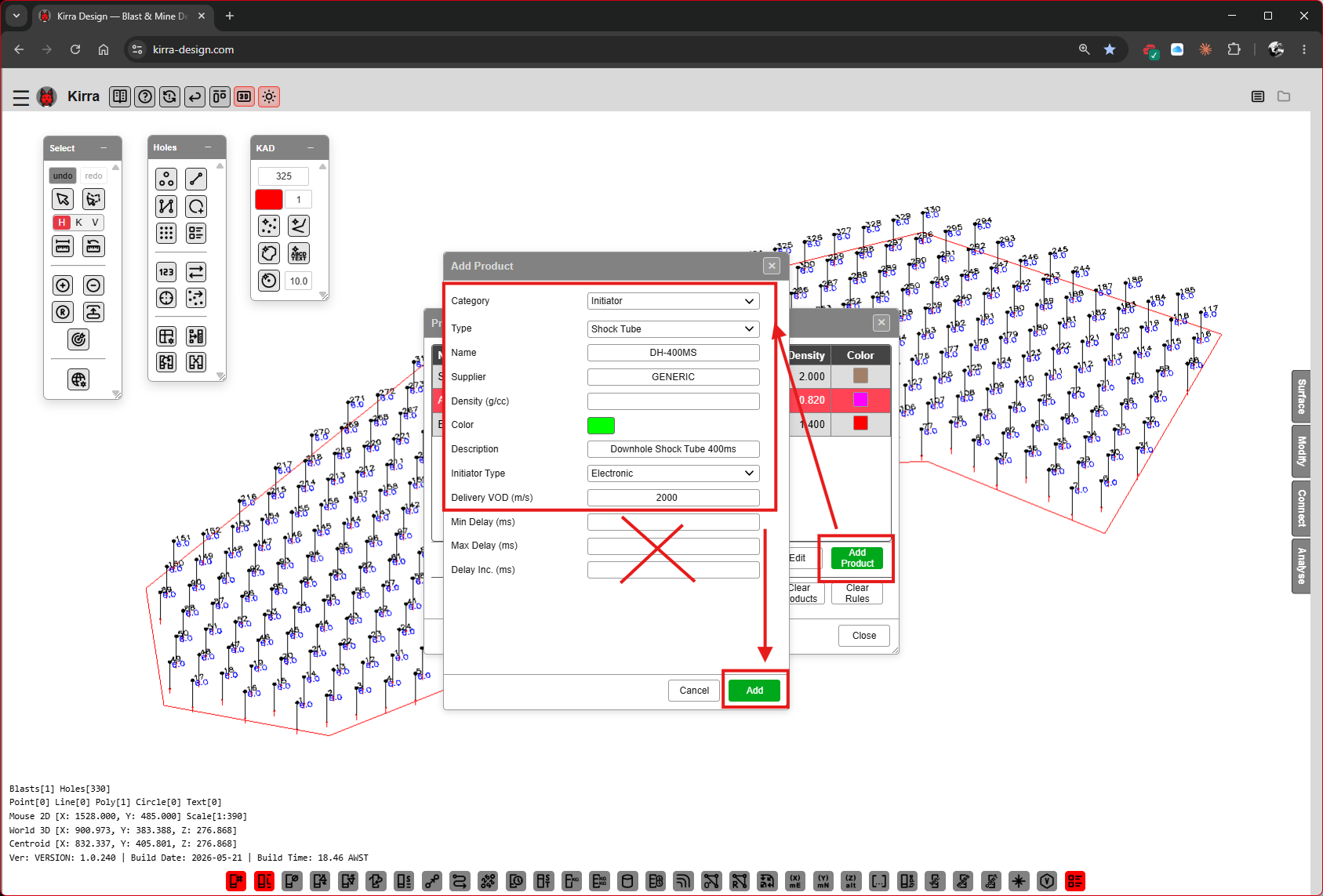
| Field | Value |
|---|---|
| Category | Initiator |
| Type | Shock Tube |
| Name | DH-400MS |
| Supplier | GENERIC |
| Density (g/cc) | [VERIFY] |
| Color | green swatch |
| Description | Downhole Shock Tube 400ms [VERIFY exact wording] |
| Initiator Type | Downhole [VERIFY: dropdown options — Downhole / Surface] |
| Delivery VOD (m/s) | 2000 [VERIFY] |
| Delay (ms) | 400 |
| Max Delay (ms) | greyed out |
| Delay Inc (ms) | greyed out |
Click Add.
Step 6E — Product library complete
The Product Manager now lists all four products with their categories, types, densities, and colours.
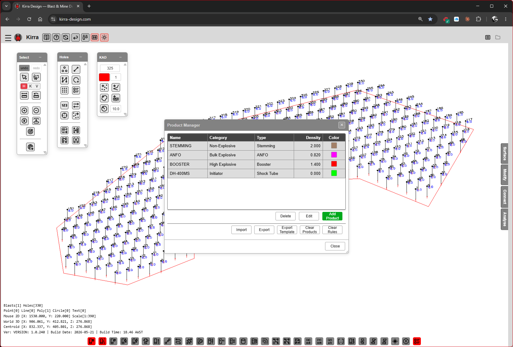 Product list: STEMMING / ANFO / BOOSTER / DH-400MS.
Click Close.
Step 7 — Build a Deck in the Deck Builder
Now that products exist, you can assemble a deck stack — the sequence of stemming, bulk explosive, primers, and any inert spacers in a single hole — and apply it to selected holes.
Step 7 — Open the Deck Builder
Open the Deck Builder dialog from the highlighted button on the Holes toolbar. The dialog has three columns:
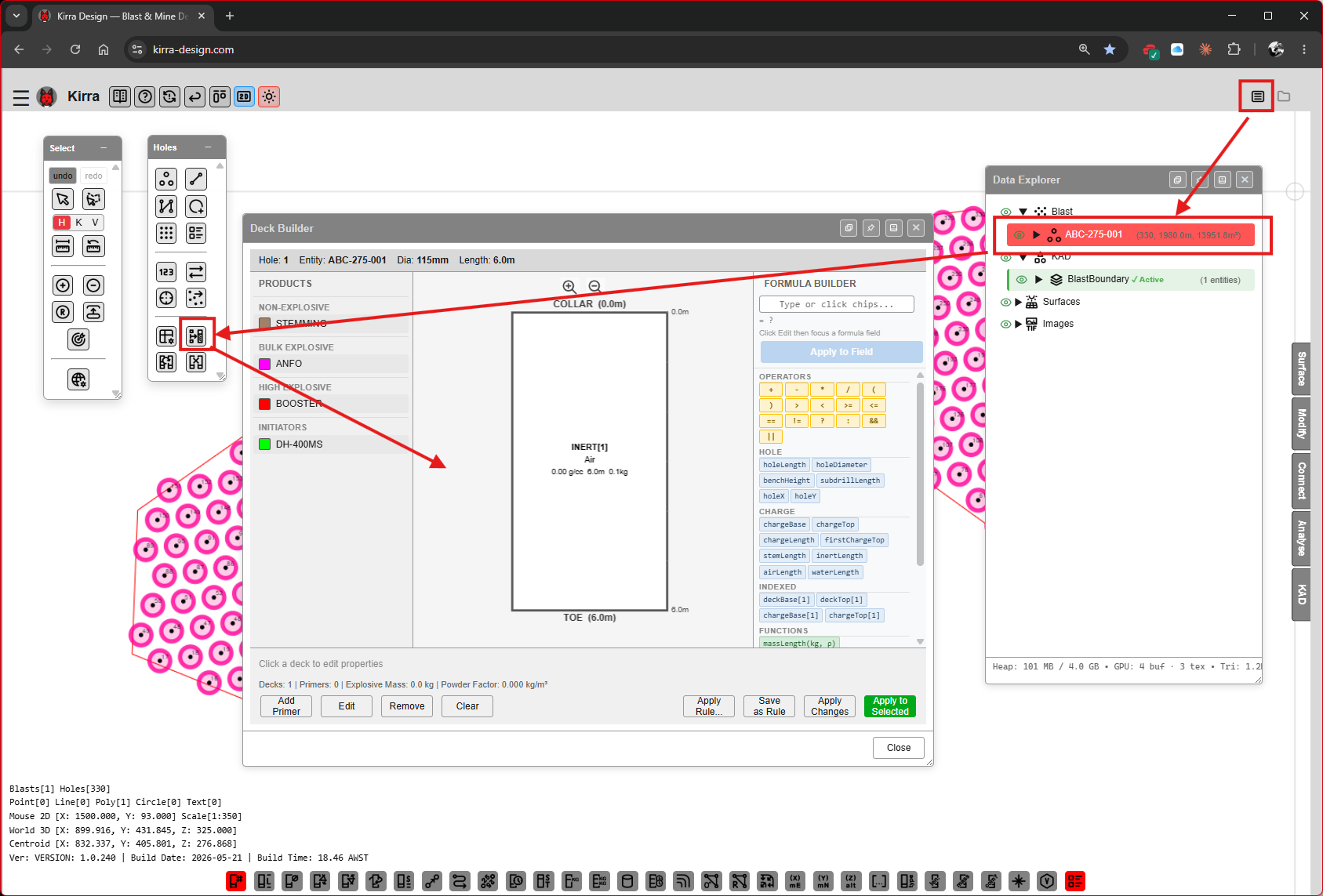
| Column | Purpose |
|---|---|
| PRODUCTS (left) | The library you built in Step 6 — drag products into the centre column |
| COLLAR (centre) | The deck stack visualised from collar (top) to toe (bottom). Shows hole header Hole: ABC-275-001 / Diam: 115mm / Length: 8.0m |
| FORMULA BULDER (right) | Click fx: formula chips to set deck base/top/length expressions |
The status row at the bottom reads: “Decks: 0 / Primers: 0 / Explosive Decks: 0 / Powder Factor: 0.000 kg/m³”.
Footer buttons: Add Primer, Edit, Remove, Clear, Fill From…, Save as Rule, Apply Changes (green), Close.
The Data Explorer on the right shows the entity tree — your blast (ABC-275-001), KAD layers, surfaces, and images.
Step 7A — Drag products into the deck
Drag products from the PRODUCTS column into the COLLAR column. The deck stack updates live.
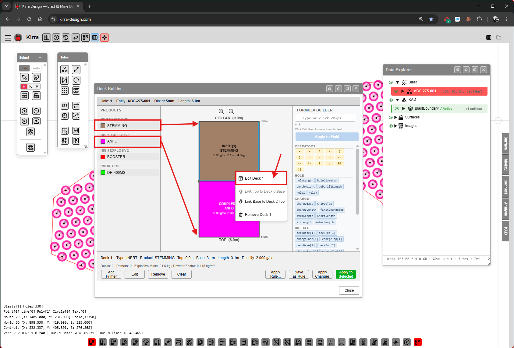 Three decks placed (STEMMING, ANFO, ANFO). Right-click a deck for Edit Deck N / Link Top to Base N / Remove Deck N.
The status row updates: “Decks: 3 / Primers: 1 / Explosive Decks: 1 / Powder Factor: 0.659 kg/m³”.
Step 7B — Set stemming geometry
Right-click the stemming deck and choose Edit Deck N to open the Edit Deck dialog.
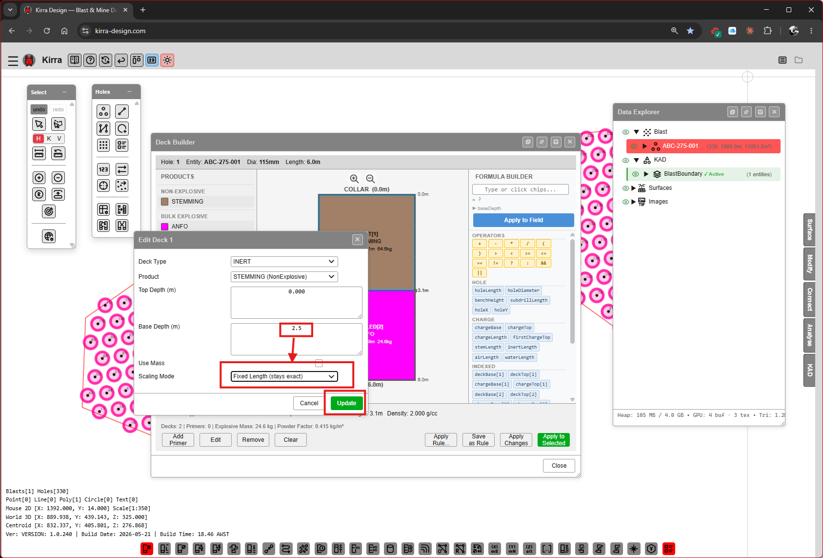
| Field | Example | Purpose |
|---|---|---|
| Deck Type | INERT |
Stemming is inert |
| Product | STEMMING |
The chosen product |
| Top Depth (m) | 0.0 |
Depth from collar |
| Base Depth (m) | 0.4 [VERIFY] |
Bottom of the stemming deck |
| Use Mass | unchecked | Drive by mass instead of length |
| Scaling Mode | Fixed Length (collar end) |
How the deck scales when applied to other holes |
Click Update.
Step 7C — Right-click a deck to link or edit
Right-click any deck and use Link Top to Base N to make a deck’s top depth automatically follow the base of the deck above it. This is how a coupled charge column stays continuous when scaling.
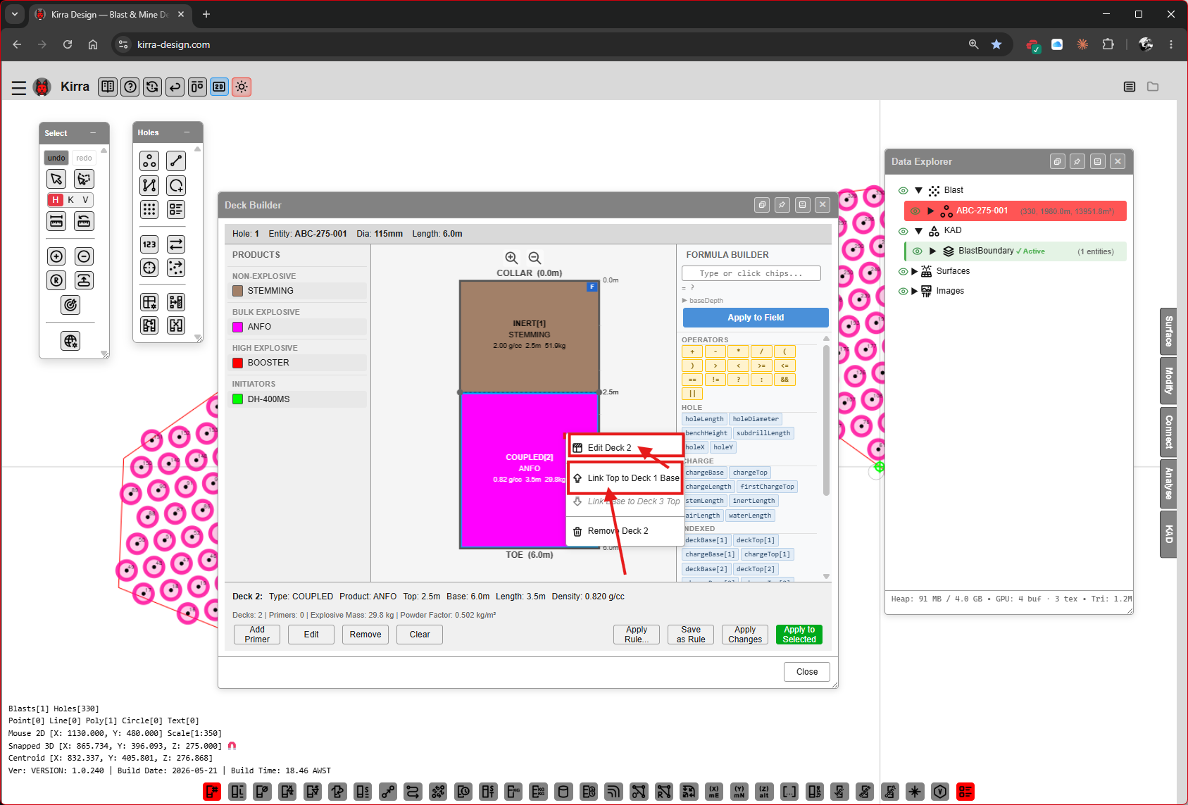 Context menu options: Edit Deck 2, Link Top to Base 2, Remove Deck 2.
Step 7D — Set the coupled deck
Edit the coupled (ANFO) deck to set its base depth and scaling mode.
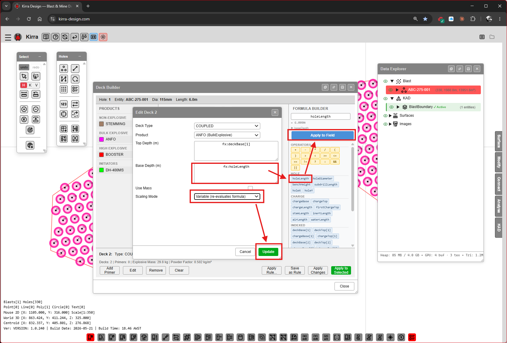
| Field | Example | Purpose |
|---|---|---|
| Deck Type | COUPLED |
Bulk-loaded against the hole wall |
| Product | ANFO (Built-in product) |
The chosen product |
| Top Depth (m) | 0.4 |
Locked when Link Top to Base is set |
| Base Depth (m) | (formula) | E.g. fx: holeLength to reach the toe |
| Use Mass | unchecked | |
| Scaling Mode | Variable — cumulative formula [VERIFY exact label] |
Variable scaling lets the deck stretch when applied to a longer hole |
Click Update.
Step 7E — Add a primer
Click the Add Primer button at the bottom of the Deck Builder to open the Add Primer dialog.
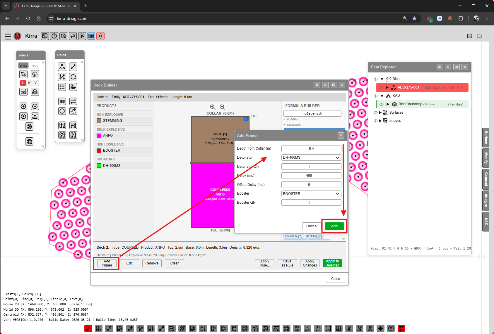
| Field | Example | Purpose |
|---|---|---|
| Depth from Collar (m) | (formula) | Where the primer sits along the column — typically fx: holeLength - 0.6 for a base-priming layout |
| Detonator | DH-400MS |
The downhole initiator product |
| Diameter [VERIFY label] | [VERIFY] | Primer / booster diameter |
| Booster | BOOSTER |
Booster product |
| Length | [VERIFY] | Booster length |
| Position | Bottom [VERIFY: dropdown options] |
Primer position relative to the deck |
Click Add.
Step 7F — Apply charges to the selected holes
Click Apply Changes (green button, bottom right). A confirmation dialog appears.
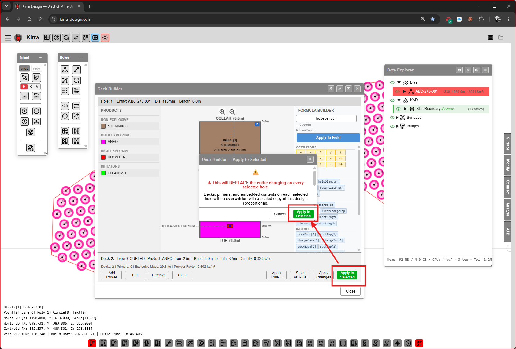 “Deck Builder — Apply to Selected” — “This will REPLACE the entire charging assignment on each of the currently selected holes. Decks, primers, and properties on each selected hole will be overwritten with a scaled copy of this design.”
Click the confirmation button to commit. Variable-scaled decks are recomputed per hole length using each hole’s actual length.
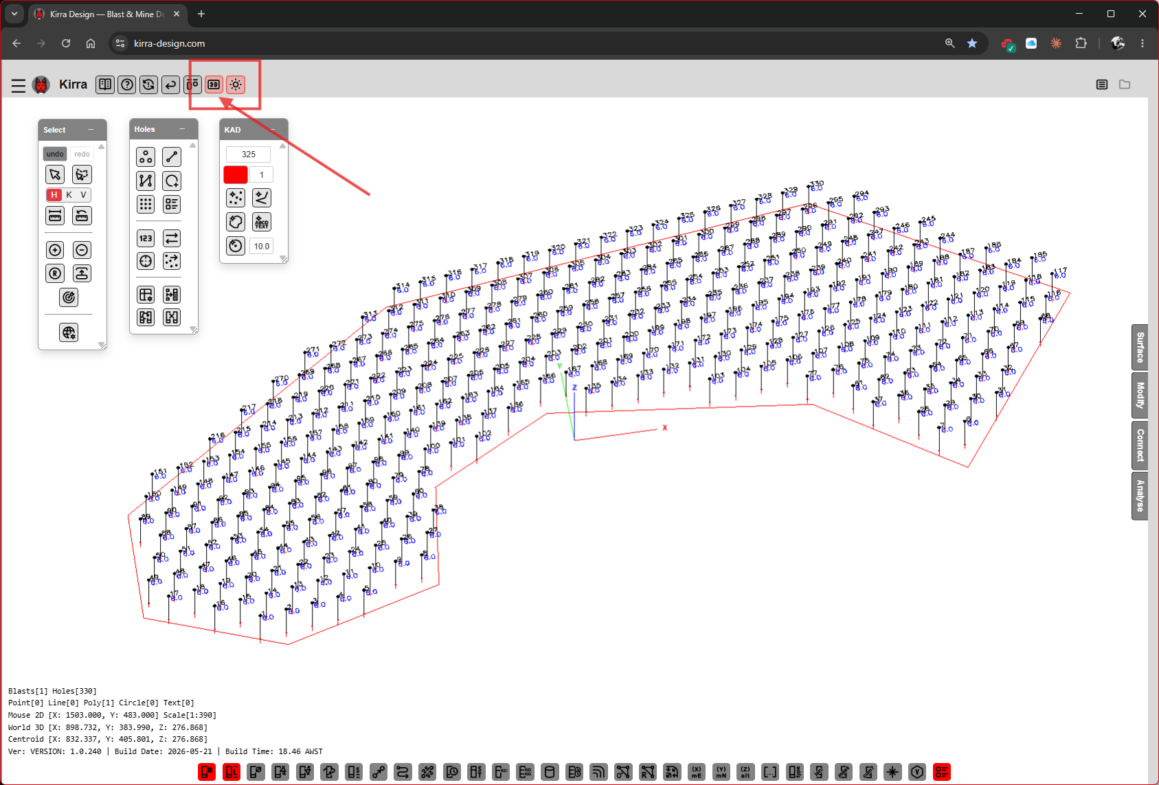
Step 7G — Holes are charged
Switch to 3D (or rotate the canvas) and your pattern is now visibly loaded — magenta / pink columns show the explosive decks, brown caps show the stemming.
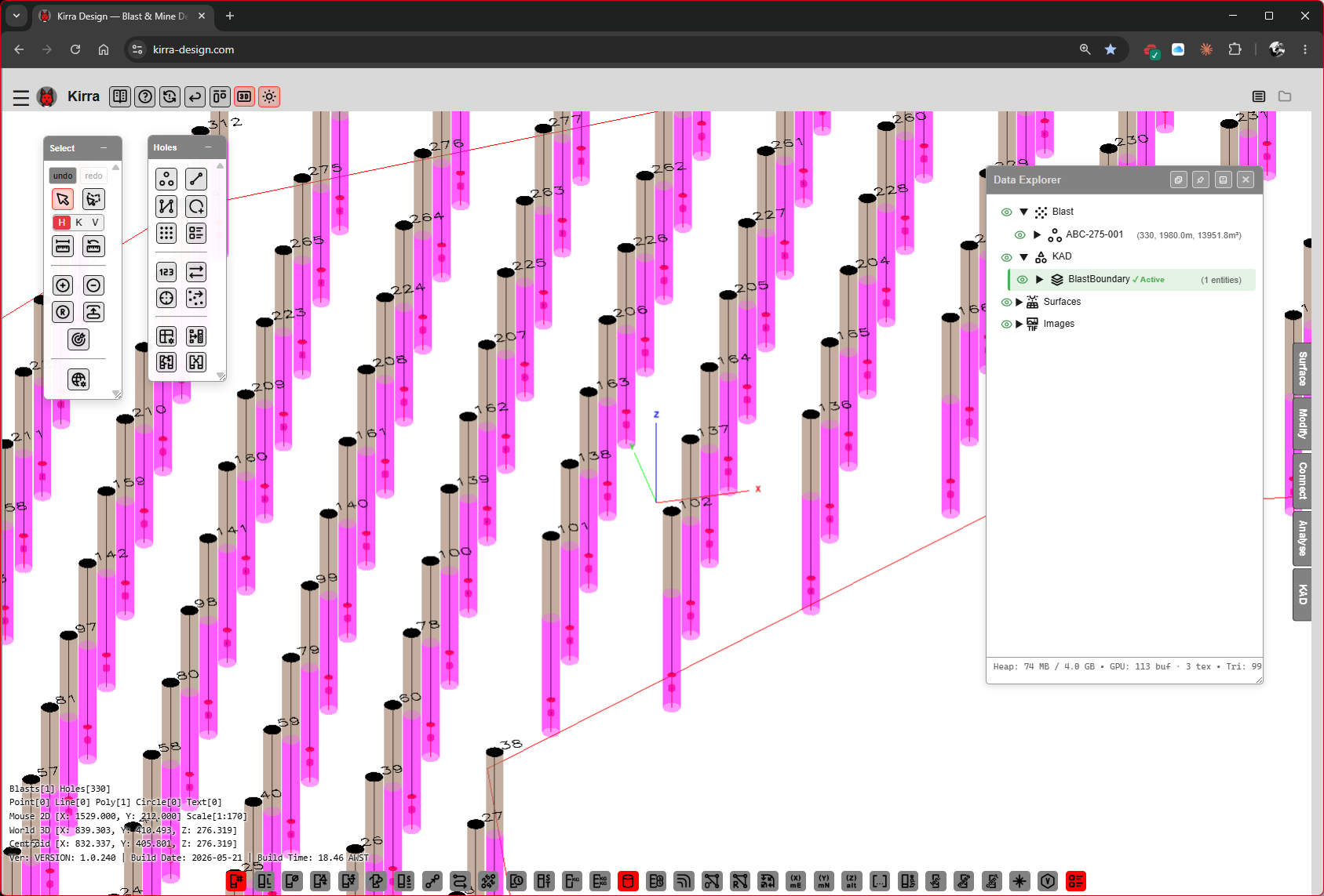 Charged pattern in 3D. The Data Explorer shows each hole’s deck breakdown.
See Charging Overview, Deck Builder, and Charge Rules for advanced workflows (charge rules, formulas, conditional decks).
Step 8 — Add Surface Connector Products
Connectors are themselves Products in the Product Manager (category Initiator, type Shock Tube with Initiator Type = Surface Connector [VERIFY exact label]). Add the surface connectors you intend to use before drawing connections.
Open the Product Manager again and click Add.
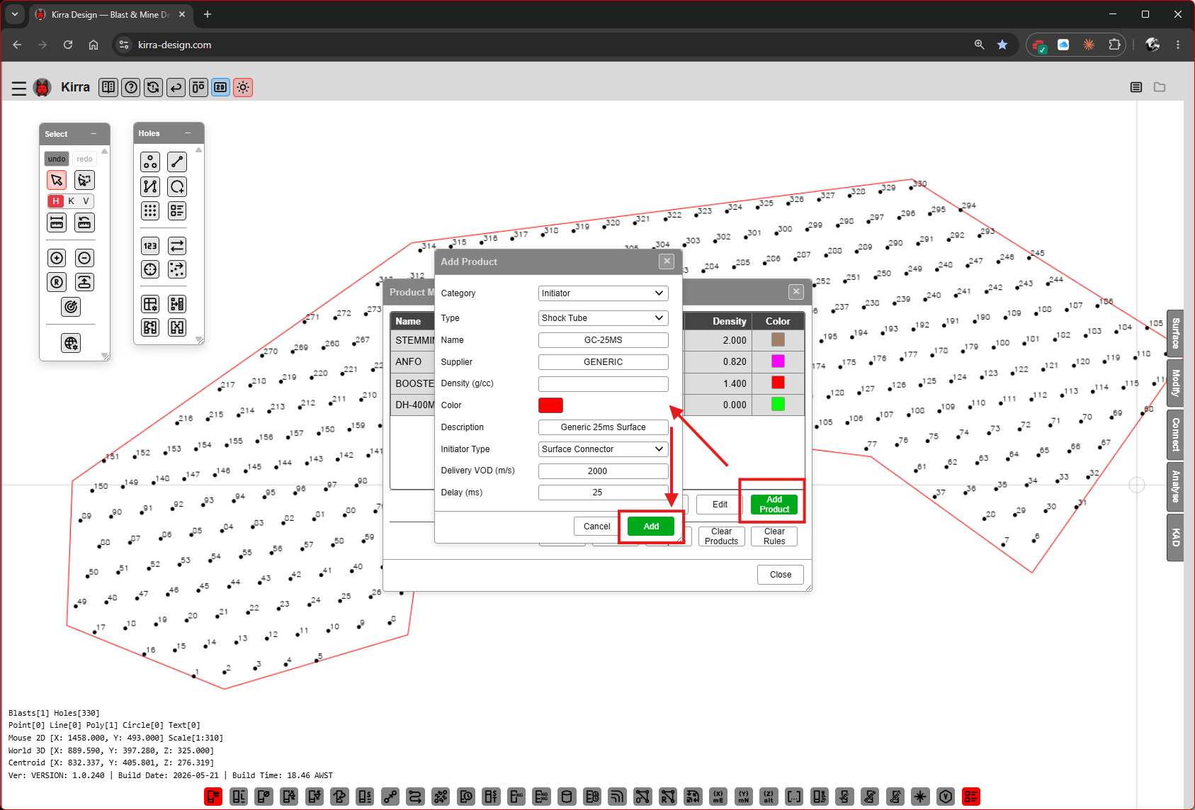
| Field | Example | Purpose |
|---|---|---|
| Category | Initiator |
|
| Type | Shock Tube |
|
| Name | SC-25MS |
|
| Supplier | GENERIC |
|
| Density (g/cc) | [VERIFY] | |
| Color | swatch | |
| Description | Generic 25ms Surface [VERIFY exact wording] |
|
| Initiator Type | Surface Connector |
This is what makes it a surface connector, not a downhole det |
| Delivery VOD (m/s) | 2000 [VERIFY] |
|
| Delay (ms) | 25 |
Click Add. Repeat for any other delays you need (e.g. SC-9MS, SC-17MS, SC-42MS, SC-67MS, SC-109MS).
Step 8B — Connector products in the library
The Product Manager list now contains your downhole det and a stack of surface connector products.
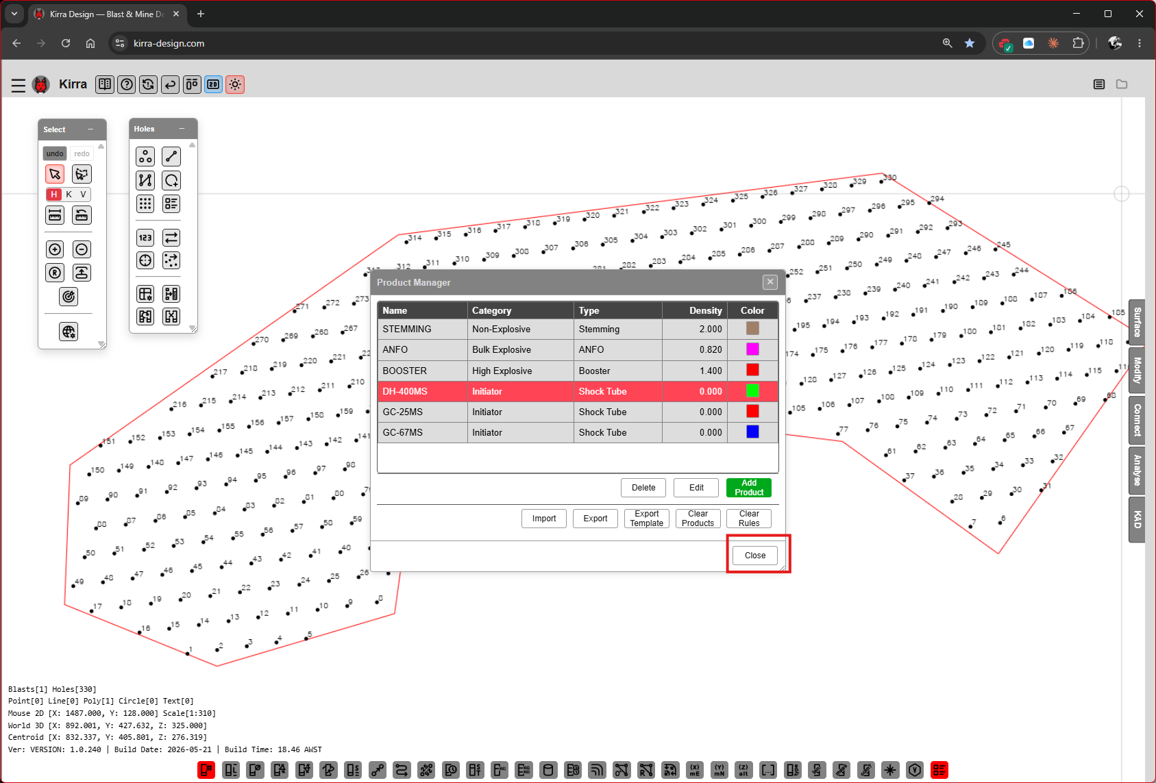
Close the Product Manager.
Step 9 — Draw the Timing Connections
Open the Connect floating toolbar (right side of the workspace).
Step 9A — Pick a connector and the connect tool
The Connect toolbar’s Product Database list (vertical chips at the bottom) shows every Initiator-type product. Click a chip to set it as the active connector — 25ms in the screenshot.
Pick the connector drawing tool you want (Single, Multi, or Continuous), then click source hole → target hole to lay down a connector line.
 Connect toolbar with
 25ms active. The green arrow on canvas shows a single connector being drawn from one hole to the next.
For row-by-row tie-ups, use Continuous Connect Holes (HW) — click each hole in sequence and press Escape to end the chain. The tool stays active for the next chain.
Step 9B — Pattern fully connected
Once every hole is in a timing chain, blue arrows show the firing direction across the pattern.
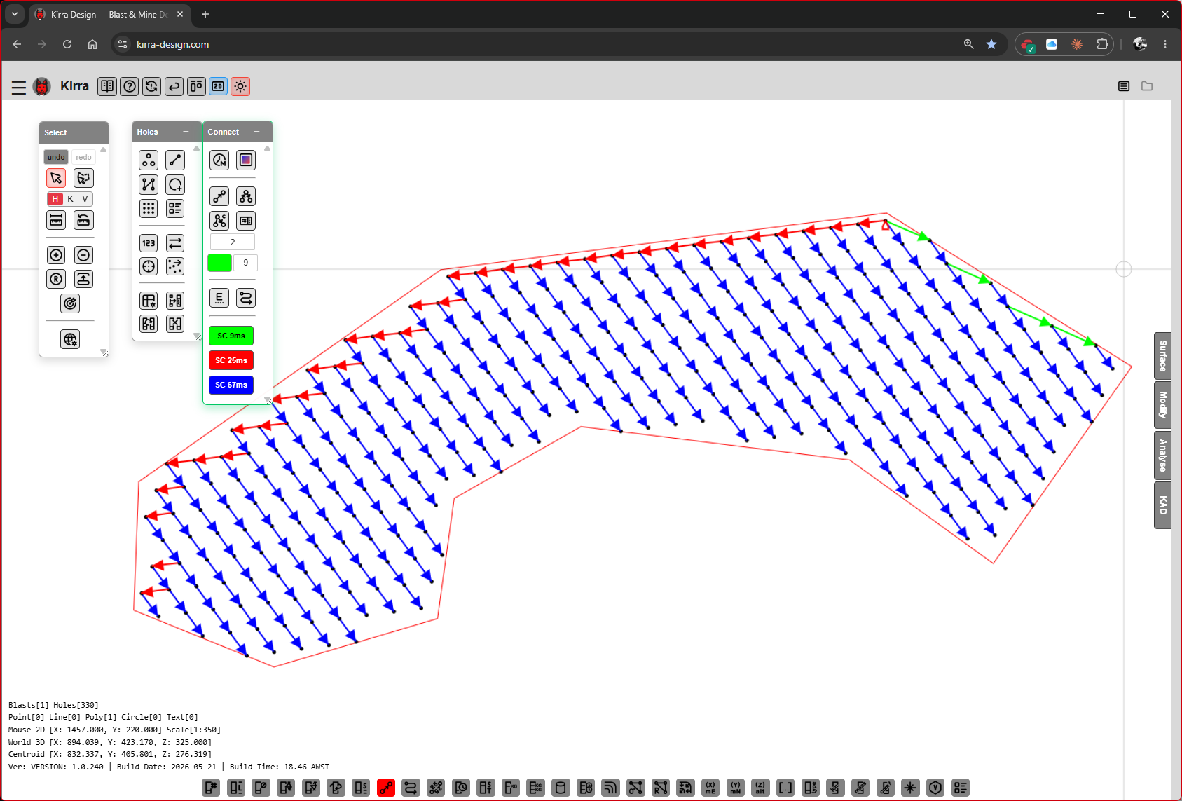 Blue arrows indicate the surface timing cascade across the whole pattern.
See Connect Toolbar for the full tool reference and Timing Sequences for timing concepts (inter-hole / inter-row delay, echelon, V-cut).
Step 10 — Animate the Blast
Open the Analyse floating toolbar and click Blast Animation Simple (highlighted in red). A Blast Animation panel appears at the bottom of the viewport with play controls and a timeline scrubber.
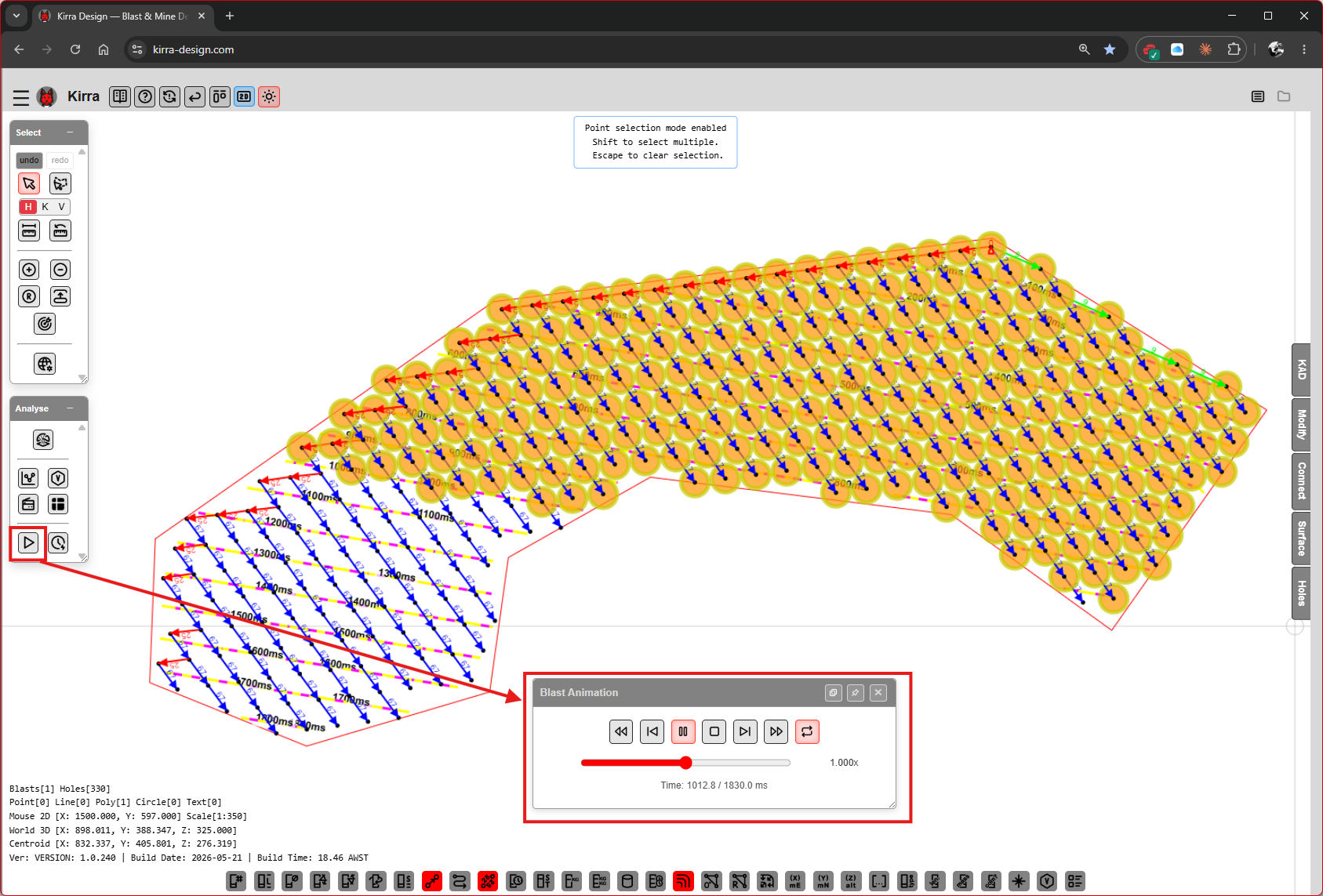 Animation playback — holes light up in firing order (yellow/orange/red along the cascade) at the time shown on the scrubber (
Time: 10.0s / 25.0 sec in this frame).
| Control | Purpose |
|---|---|
| ⏮ Skip to start | Reset to t=0 |
| ⏸ / ▶ Play / Pause | Toggle animation |
| ⏭ Skip to end | Jump to last hole’s fire time |
| Timeline scrubber | Drag to a specific time |
| Speed control | Playback rate [VERIFY: speed control button presence and options] |
The hole colour ramp reflects firing order — earlier-firing holes are cool colours, later-firing holes are warm.
For deeper timing analysis, use the Time Window dialog from the Analyse toolbar — see Time Window Dialog.
Where to Next
You now have a complete blast: pattern from template, charged holes, timing cascade, and an animation that plays back the firing sequence. Common next steps:
| Goal | Where |
|---|---|
| Run vibration / PPV analysis | Analyse Toolbar → Blast Shader Tools, Voronoi Options |
| Frequency-domain / detune analysis | Time Window Dialog (IDI, Spectrum, Forward Array, Detune, Constrain) |
| Flyrock shroud | Flyrock Modelling |
| Save the project | App Navigation panel → File Management → Export → KAP |
| Generate a print sheet | App Navigation panel → Print Management → Print Dialog — see Print to PDF and XLSX Templates |
| Export to CSV / DXF / IREDES | App Navigation panel → File Management → Export — see CSV Export, DXF Export, Other Formats |
Summary
| Step | Action |
|---|---|
| 1 | Open the Pattern Templates dialog (Holes toolbar) |
| 2 | Add a template — diameter, burden, spacing, sub-drill, direction |
| 3 | Save and close the templates library |
| 4 | Place a rectangular block of holes using the template |
| 5 | Alternative: draw a polygon and fill it with holes |
| 6 | Build the product library (stemming, bulk, booster, det) |
| 7 | Build a deck in the Deck Builder and apply it to selected holes |
| 8 | Add surface connector products to the library |
| 9 | Draw the timing cascade with the Connect toolbar |
| 10 | Animate the blast from the Analyse toolbar |
| *← Overview | Interface Tour →* |